Common iOS Interview Questions

Many technical companies, particularly ones that require plenty of problem solving like to pose technical problems to interviewees to gauge how it is they think through potential problems they’ll run into at their new job. Although the answer themselves aren’t necessarily as important as your ability to display how you think through these problems, having a few practiced out can help with what can be a stressful situation.

Question 1: Algorithm Questions

Interviewers love to give algorithm questions, and this is because they test two things: 1. They test how many types of typical computing problems you’ve encountered before, and 2. they let you gauge problem solving skills. In software development a lot of solutions are simply rephrased solutions to typical problems. Look at arrays, anyone who’s used them for any amount of time has probably run into several of these problems already. Enumerating arrays, sorting them , finding an element, etc. If you can’t come up with a potential solution to these problems then that is very scary to an employer. More importantly however is that you demonstrate the ability to tackle the problem if you don’t know right off the bat how to solve it. In this example I’ll give the one I’ve been asked and heard of people being asked the most.

In objective C a lot if not all of our list organization is done with NSCollections, but there are other data structures that have their own pros and cons to arrays. In this case it is the linked list. Instead of having every element of the list lined up in order after the first list element, each element contains at least two pieces of information: The object the list node stores, and a pointer to the next list node. Then there’s also the doubly linked list which simply has an additional pointer that points to the previous list node.

linked_list

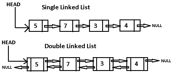
Remember even though you may not have the best solution to this problem already, you should be able to formulate a plan to how you might solve this, and it’s your ability to do this that’s most important. I might ask myself, how does a linked list iterate through itself? It does so by having a pointer pointing to the current node, and for every iteration, it becomes the current node’s next node. OK, now how do we know if the list is looped? Well how about we draw a node diagram with a loop to help us?looped list

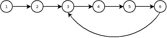
Now the problem becomes more clear. I know the most optimal solution, but previously I’ve answered this problem by adding a boolean for each node that remembers if the function has iterated through the current node yet, and if it has you know the list is looped. The optimal solution, which you may or may not arrive at yourself in the allotted time is to have two pointers going through the loop, one that grabs the next list node for each iteration, and one that grabs the next-next list node. This way, when you go through the list, one will do so at twice the speed. If there is a loop in the list then the fast pointer will eventually point to the same node, and when it does you return that the list is in fact a loop. And if any of the pointers reach a null, then you know you’ve reached the end of a list and haven’t looped.

boolean hasLoop(Node first) {

    // list does not exist..so no loop either.
    if(first == null) 
        return false;

    Node slow, fast; // create two references.

    // make both refer to the start of the list
    slow = fast = first;

    while(true) {

        slow = slow.next; // 1 hop.

        if(fast.next != null)
            fast = fast.next.next; // 2 hops.
        else
            return false;  // next node null => no loop.

        // if either hits a null pointer, it's not a
        if(slow == null || fast == null)  loop.
            return false;

        // if the two ever meet...we must have a loop. 
        if(slow == fast)             
            return true;
    }
}

I personally wouldn’t implement this in objective c, since this isn’t ever a problem you’d run into since this is all implemented for you. However if you have to inline new functions for whatever reason this is how you’d do it in C++. Even though iOS handles this all within its core framework, being able to go through the steps to solve this problem goes a long way towards demonstrating the right problem solving skills that iOS developers are expected to have.

Question #2 : Faulty Code Questions

Many times employers will come prepared with samples of code that have a known problem in it and its up to you to figure it out. Considering that much of your time as a developer is spent debugging code of your own or sometimes even code that others have written, this is an important skill to demonstrate.

Imagine you wanted to record the time that your application was launched, so you created a class that defined a global variable in its header: NSString *startTime;. Then, in the class’ implementation, you set the variable as follows:

+ (void)initialize {
    NSDateFormatter *formatter = [[NSDateFormatter alloc] init];
    [formatter setDateStyle:NSDateFormatterNoStyle];
    [formatter setTimeStyle:NSDateFormatterMediumStyle];
    startTime = [formatter stringFromDate:[NSDate date]];
}

If you then added the following line to the application:didFinishLaunchingWithOptions:method in your AppDelegate:

NSLog(@"Application was launched at: %@", startTime);

what would you expect to be logged in the debugger console? How could you fix this to work as expected?

The problem with this code is that the global date object, startTime was never set.

Question 3: Under the hood functionality

There are many situations where understanding how the program  is beneficial. One question that seems to come up very frequently on blogs and developers websites seems to relate to the ARC (Automated Reference Counter) which determines what referenced objects aren’t being used any more and can be removed from memory. Retain counts are the way in which memory is managed in Objective-C. When you create an object, it has a retain count of 1. When you send an object a retain message, its retain count is incremented by 1. When you send an object a release message, its retain count is decremented by 1. When you send an object a autorelease message, its retain count is decremented by 1 at some stage in the future. If an objectʼs retain count is reduced to 0, it is deallocated.

This will explain how the memory management is done in iOS

Introduction to Digital Systems & Computer Architecture

Introduction

Switching my primary career focus from Electrical Engineering to Software Development I’m told I have a pretty unique perspective on working with computing systems. I tend to agree, although I wish I had come to realize that I would be more fulfilled writing software than working with computer hardware, I do have an appreciation for the knowledge of how these lines of code become binary sequences that tell a computer how to perform the desired actions that a program will give it.

Abstraction

The reason that many software developers don’t know these details is mostly due to abstraction. One reason we abstract things is so that we can focus on the correct scope of actions so that we get the desired work done with minimal effort. If we didn’t, we’d probably still be loading decks of punchcards into our computers to tell them what it is we want them to do; not ideal. Fortunately as our computers’ capabilities evolved, how we interact with them has evolved with them, and this is largely due to continuing abstraction. In this series of blog posts I hope to bridge the gap of knowledge between the software developer writing code for his computers and how that code eventually becomes the correct sequence of binary signals stored as programs, and how computers convert that program into the desired outputs they were programmed for. I will start by showing how transistors work, and how they are used to design basic digital circuits, then I will show how these basic digital circuits form the basic components of a computer such as memory, computational units and data path, and then finally I will show how programs are turned into binary instructions for these computers to work with.

The Transistor

We’ll begin this exploration for how computers turn code into the desired output, through a bottom up approach, by starting with the Transistor. Just how the building blocks of matter are the atoms they are composed of, the building blocks of digital systems are the transistor.  Transistors are formed out of semiconductors, usually differently concentrated silicon. Due to silicon’s atomic nature it can be induced to have slight electrical biases, that is to prefer positive or negative charges at extremely minute levels. N-type silicon is silicon that has slightly more electrons within the substrate than a neutral charge, and vice versa for p-type, with what we call holes. When these types of silicon are combined in the way shown in the diagram below we get what’s called a MOSFET – Metal Oxide Substrate Field Effect Transistor, the type of transistors most commonly found within CPU’s.

A MOSFET - the most common transistor
Composition of a MOSFET
Schematic Symbol for MOSFETs
Although transistors can also be used in analog systems, we are only concerned with how they work as digital switches. Think of them as water valves, the more you twist or push the valve, the more water that can flow. The valve in question is usually called the gate on MOSFET, and the pipe has two pins – the drain and source. When the gate of a transistor is stimulated, either by an increase in current or voltage, the electron channel between the drain and source will open. This is due to the electrons the gate is drawing starts the equalize the charge in the channel between the drain and source. This allows the channel of the MOSFET to freely allow current to flow.
Transistor Logic
Now that we understand how transistors work, we can start to show how they are combined to form some basic logic functions, or logic gates. You have probably heard of the most basic ones: NOT, AND, NAND, OR, NOR & XOR. You should know how AND, OR, & NOT function, but maybe not the others. NAND is simply an inverted AND; the only output that isn’t true, is when both inputs are false. The same goes for NOR; only when both inputs are false is it true. XOR is also known as the comparator. It is only true when the inputs are at different states.
The diagram symbols for the basic logic gates

These gates can all be made by using transistors in certain design patters that can be repeated for each and every logic gate required. They are shown below for the AND, OR, NOT gates.

CMOS Inverter a.k.a. a NOT Gate
CMOS Inverter
CMOS AND Gate
CMOS AND Gate
A CMOS OR Gate
A CMOS OR Gate

Designing Digital Circuits

The way we design digital logic circuits is by analyzing truth tables. When we design logical circuits we know the end result of the logic circuit that we want, and we know the input to that circuit that should give us that result. We organize this information with truth tables, like the one below, to help us visualize the combinational logic for the circuit. To show how computation can be performed with logic circuits we’ll go through the design for a single bit adder. Below there’s the block diagram showing the inputs and outputs for a full adder. You need the two bits to be added ‘A’ & ‘B’, a Carry-in ‘Cin’ (more on this later), a Sum output ‘S’, and Carry-out (Cout). You may be confused by the carry input and outputs, but bare with me. The carry out is there to represent how we have to carry a number between digits while adding. Just like in the decimal number system we have to carry a ‘1’ over to the next digit if the sum exceeds ‘9’ on that digit, binary is just the same. The only difference is that in a binary number system we carry the ‘1’ if the sum goes beyond just ‘1’. The carry in bit is just the input that accepts the carry out from the previous digit so that it gets accounted for in the sum.

Block diagram for a 1-bit adder
Truth table for the adder. Note the positive sum outcomes are red and the carry blue.

Now that we have the desired truth table its time to deconstruct the logic we need to make this function work as intended. We usually do this by examining which outputs have a ‘1’ and noting what combination of inputs give us this output. The combination of inputs that give a ‘true’ output for the sum bit are  colored red, while the carry out bit is colored blue, and the one combination that makes both true is purple. If we represent AND’ed inputs as a products symbolically, OR’ed inputs as a sum, and NOT’ed inputs as a bar over the input letter, we get this equation for the Sum bit and the Carry bit. The circle with the cross is the XOR function and we arrive at its use by noting which bits are different at the inputs, and they are preferable to AND or OR gates because they usually require fewer transistors.

Equation for sum bit
Equation for carry out bit

This equation now can tell us what the logic circuit will look like. If we examine each function in order we see that for the sum, A XOR B XOR Cin = Sum. For Cout we see that A XOR B, then AND’ed with Cin, then OR’ed with A AND B.

Adder Circuit
Adder Circuit
A single bit addition isn’t all that useful, and hardly worth all the effort it takes to design and manufacture these chips. So we now need to combine these functional blocks to make something more useful. In this example we will design what’s known as a ripple-carry adder. Sticking with the theme of abstraction, we will now abstract all the nitty gritty transistor and gate level design work we performed previously by simplifying the single bit adder to one single functional block, which by itself represents 28 transistors. If we consider how we add decimal numbers together that are more than one digit it becomes pretty clear that we need to feed these functional blocks into each other with the carry outputs into a sequence and each consecutive sum output will then represent a binary digit of one higher order. The result is shown below. A1 is summed with B1, A2 with B2, A3 with B3 and A4 with B4. Now we have 2 4bit inputs that give us a 4-bit output representing their sum and a carry out bit incase we overflow.
4bit Ripple-Carry Adder
Summary
In summary we have gone through how transistors can create basic logic functions, how these logic functions represented as logic gates can be used to create useful combinational logic functions such as an addition, and how these functional blocks can be combined to perform actually useful functions. If you were to make a circuit out of this design you would indeed get the desired addition function that was initially intended and you can see a demonstration below of someone that put together this circuit and tested it.
Next time I will cover how these functional blocks can be combined to form the basic parts of a computer. Hopefully the this will help close the gap of abstraction that separates the programmer from the computer architect.

[Obj C] patternBuffer[0]: Learn Objective C using Previous Programming Languages

Foreword: As I was learning how to develop for iOS I was disappointed to not find many tutorials or articles that were written for people who already have experience with other object oriented languages such as C++, Python, Java, etc. If you already have experience programming the many common patterns and structures that software developers use, but in another language it would be nice to simply see how those patterns appear in the new language being learned. That is what I’m going to do with the pattern buffer series for objective c, aka [Obj c] and I will begin with the basics of defining, declaring and calling basic variables, objects and methods.

A brief history of…

Objective C was designed to be completely backwards compatible with standard (non object-oriented) C but using Small Talk derivative mechanics of object orientation to expand on it’s capabilities, in particular it uses the message model of object orientation. These were all concepts that the Xerox XPARC research division had developed, along with ideas such as the GUI that Apple had eventually acquired before they’re personal computers took off in the early 80’s. Objective C itself was initially developed by a now defunct personal computer firm called NextStep, whose name you will become intimately familiar developing in this language. When they wrote the foundation framework for this language they came up with a standard naming convention for objects from the foundation library by giving the “NS” prefix to any object or variable that comes from the foundation objective c library. NextStep was eventually acquired by Apple and has since been their primary language for developing applications for not just their personal computer operating systems, but also now for their phones, tablets, wearables, and home devices.

The Basic place to start for a new programmer of a language is of course the infamous “Hello World!” program, so here we will keep with tradition by explaining how this program is written (for the terminal) in Objective C and compare it to C++, Python and Java.

In C++ developers typically use the “iostream” standard library to communicate with the console.


#include