Decoding the MTA

The New York Subway system also known as the MTA is a highly outdated and probably the most complex subway system in the world. Trying to make applications that help commuters get through this complicated network of rails is even more complicated than learning how to navigate this tricky rail network.

What Data is Available?
Unfortunately real time data from the MTA is quite scant. For what ever reason in the age of information the MTA has only saw fit to equip the 1-6 and ‘L’ routes with sensors and shared that information with the public and even then arrival predictions are usually off by at least a minute. Meanwhile in Tokyo several millions are transported to/from 197 stops so timely and reliably that they give you late passes to prove to your boss that the trains were the reason you were late.

Back here in New York, predicting the arrival and departure times of all the trains is very difficult if not impossible depending on how accurate you want to be. That is the problem my team of developers from the Flatiron School and I are hoping to solve with our app codenamed: SubWaze.

Waze for SubWaze
As our codename implies SubWaze is an app that hopes to tackle the lack of real-time data in the New York Mass Transit network by adapting the techniques the wildly popular driving/navigation app Waze uses to collect crowd-sourced data about our road networks to improve the driving experience for everyone using the app. By encouraging users to report everything from speed-traps, to accidents and potholes and having other users verify or disprove those claims Waze has managed to create extremely detailed and constantly changing roadmaps that allows the app to warn you about said speed-traps, accidents and potholes before you run into them. I’m sure by now they’ve saved me at least one or two speeding tickets. Anyways, our app hopes to take this same concept and apply it to our city’s highly frustrating public transportation network and make better notifications of service changes, delays and give people the best real-time routes they can take to get through our great city.

The first stumbling block we’ve encountered was how to acquire all of the MTA’s timetables and what real-time data that they do provide. The real-time data will be covered later as the techniques used to download, decode, and parse the data are a little bit different than the static time-tables for all trains’ expected departure and arrival times at all stations.

GTFS
Google lead the quite possibly first large and organized effort to create a standard protocol for encapsulating a transportation network’s data. Their end result is called GTFS or General Transit Feed Specification.

The MTA implementation of GTFS
The MTA follows the GTFS standard for the most part. It uses a lot of the same conventions of language, and the same CSV files. They provide almost no documentation to these files and doesn’t even bother to mention that they follow the GTFS model nor that they differ in a few tricky places. Here I will hope to clarify how to use the data they provide in case you need this information for your own applications.

A word about language
This data becomes much easier to understand when you learn the naming conventions that this data follows. A route is the collection of stops that are linked together, for example here in New York the ‘1’, ‘N’, ‘L’, etc. are all different routes. Stops are, in the case of New York subways, places like Union Square, Bowling Green, Bedford Ave., etc. that a subway or bus or railway will stop at to pick up and drop off passangers. Trips are the numerous travels a train will take from its starting stop (not necessarily the same as the route starting stop) to its ending stop (again not necessarily the same as a route’s) that are separated by the stop_times that they have at each stop. Stop_times are the most important data element that they give you because they relate different stops to different trips and by association different routes. A stop_times are the list of times that a trip arrives and departs from a particular stop.

ta_data_model_diagram

A Database Comes To Mind
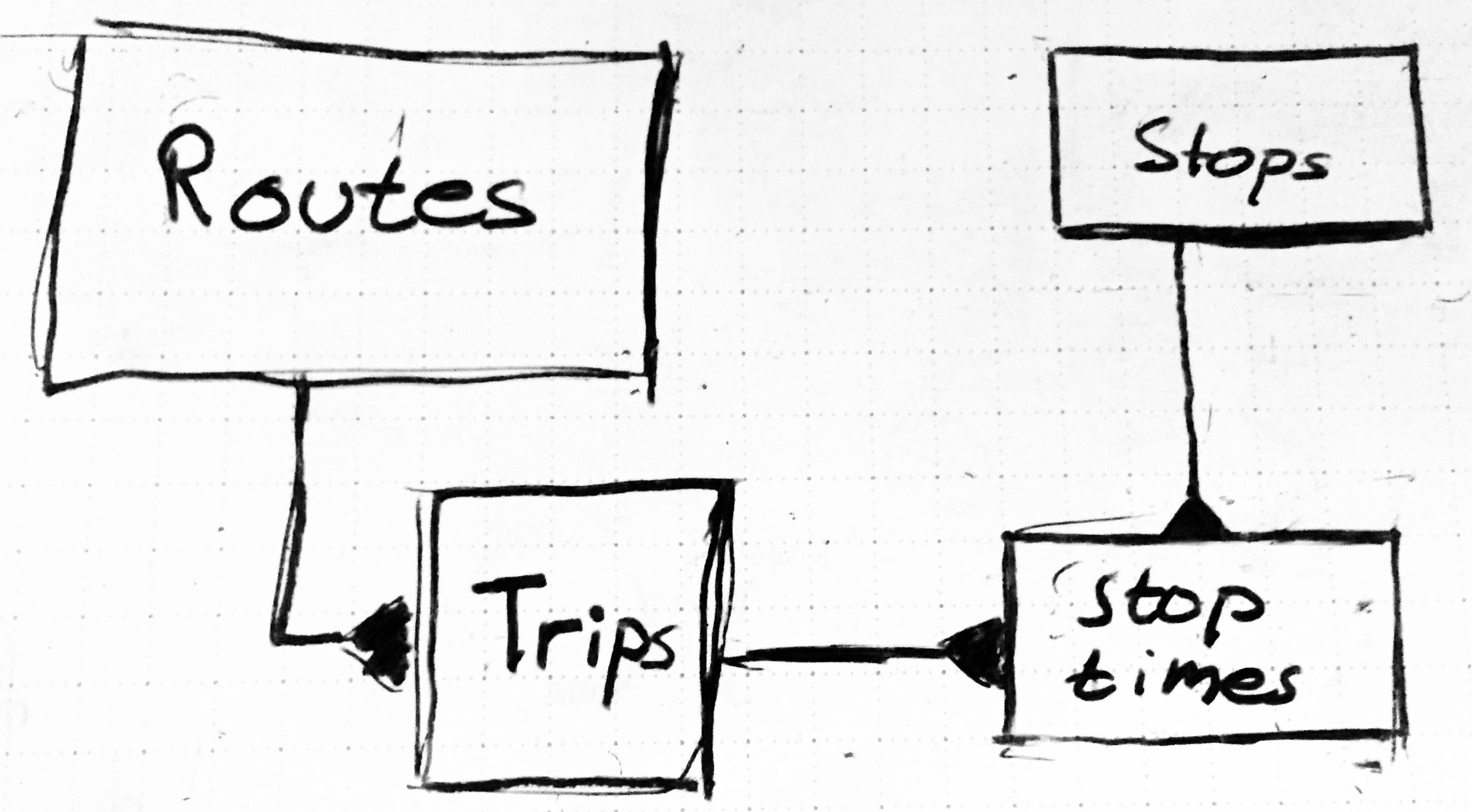
As this language starts becoming clearer a certain relational database model starts to become more clear and the one we’ve implemented in our app is detailed in the diagram above.


MTA Data Model Relationships – Note: Triangles indicate that there are many objects connected in the relationship. So for routes there are several trips related to one route.

routes.csv

  • route_id
    • The id used to find what route a trips object relates to
  • agency_id
    • Should always be MTA_NYCT probably unimportant
  • route_short_name
    • route_long_name
  • route_desc
  • route_type
    • almost always ‘1’ with exception of the Staten Island Railway
  • route_url
    • url leading to a pdf with the route’s information
  • route_color
    • A hexadecimal describing the color associated with the route, i.e the 4 is green
  • route_text_color
    • hexadecimal associated with the text color used to display the name of the route
    • most of these entries are blank, and three are ffffff
    • it is probably safe to ignore this value

trips.csv

  • route_id
    • links with the route_id of routes.cvs above
  • many trips belong to one route_id
  • service_id
  • we don’t care about this field….?
  • trip_headsign
  • The final stop on the trip, think of the headsign you’d see on the train to determine if you’re – getting on the train going in the right direction
  • direction_id
    • a ‘1’ or ‘0’
    • consider it a boolean
    • used to indicate which direction the train taking the current trip is going
  • block_id
    • empty
  • shape_id
    • the unique identifier that relates this particular trip to the shape objects that trace out the path the this trip takes on a map

stops.csv

  • stop_id
    • the ID for the stop along a subway line
    • there’s three for each subway stop
    • one that is general
    • one that is northbound
    • one that is southbound
    • although there’s these three versions they all refer to the same station
    • the first number/letter refers to the subway line the stop belongs to
    • The last character refers to south or north bound or if it is a generic stop
  • stop_code
    • empty
  • stop_name
    • The official name of the stop, this would be the strings we’d want to use for to let the user select stops
  • stop_desc
    • empty
  • stop_lat
    • the latitude of the stop
  • stop_lon
    • the longitude of the stop
  • zone_id
    • empty
  • stop_url
    • empty
  • location_type
    • ‘1’ or ‘0’
    • should be a boolean
    • 1 or YES for generic tops which is treated as a parent for the north or south types
    • 0 or NO for the stops that specify north or southbound trips
      this distinction becomes clear in the next data field
  • parent_station
    • empty if it is a parent stop or the previous field ‘location_type’ is 0
    • if the previous field is 1, it simply uses the stop_id of the parent stop

stop_times.csv

  • trip_id
    • the identifier that links the stop_time to a specific trips object
    • there’s definitely hints about trip information embedded within the trip_id, but I haven’t taken – time to decipher it yet, might not be a valuable use of time?
  • arrival_time
    • the train’s arrival time at a specific stop in “HH:MM:SS” format
  • departure_time
    • the train’s departure time at a specific stop in “HH:MM:SS” format
  • stop_id
    • the identifier that links this stop time with a specific stop from the above file
    • remember the first character indicates what route this belongs to
    • the last character relates to whether it is a ‘N’ northbound train or a ‘Southbound train
  • stop_sequence
    • haven’t confirmed this yet, but I believe this relates to the order of which the stop belongs along the route
    • Number starts at 1 not 0
  • stop_headsign
    • empty
  • pickup_type
    • not sure yet
    • either ‘1’ or ‘0’ and no idea what they mean
    • probably unimportant for us
  • drop_off_type
    • same as above
  • shape_dist_traveled
    • the segment distance traveled between stops, unfortunately it is empty
    • unimportant for our app, but would be interesting data

shapes.csv
The massive list of coordinates that make up the path a route takes through the city

Thanks for listening, I hope you’ll give credit to any work me and my partners have lead you towards. Please leave comments if you liked the article, or even if you hated it, we are constantly learning. And as always…

Live Long And Prosper
Mark Haus

Swiping Table View Cells

In my opinion the best UI designs are ones that allow users access to and the ability to modify as much information in as possible in as little time as possible. A recent trend in table views has significantly expedited the process of modifying the contents of a table view very quickly and intuitively. This is a blog post about one of my favorite UI based cocoa pods, MCSwipeTableViewCell.

mugatu

Mailbox started this trend almost two years ago with their wildly popular third party e-mail app. What they do is give you a standard looking table list view with relevant mail information on each cell. However as the above diagram shows it also gives you the option to swipe the cell to trigger code blocks. In this case a swipe right reveals a check mark to mark the mail as read and remove it from the stack, and a swipe left reveals a yellow deferral option that triggers a popup menu to give you deferral choices in case you want to revisit the mail even though you wish it to disappear form the inbox stack. Now even google has gone on board and made their own implementation of this functionality with their inbox app.

MCSwipeTableViewCell

Enter the MCSwipeTableViewCell gitHub repo slash CocoaPod by AlikaRagoz. As the above gif demonstrates it gives you the option to give this functionality to any table view cell in your app and specify multiple swipe triggers for any actions you want to give them. Not only does it give you the single swipe left or right functionality of the mailbox app, it gives you different triggers at different swiping distances incase you need more functionality. The background color/icon, swipe distance, block functionality and even some delegate options are all configurable and in my app, “Tasks” I make use of these to handle task “snoozing”, completions and moving tasks from the inbox to different user generated lists.

How To Use

After creating a podfile, init’ing it, and installing your pods you will need to include it in your table view controller class. Then you need to start creating instances of the MCSwipeTableViewCell, usually within the cell dequeuing method that all table view controllers call when generating table view cells.

cell.firstTrigger = 0.1;
cell.secondTrigger = 0.6;

UIView *checkView = [self viewWithImageName:@"check"];
UIColor *greenColor = [UIColor colorWithRed:85.0 / 255.0 green:213.0 / 255.0 blue:80.0 / 255.0 alpha:1.0];

UIView *crossView = [self viewWithImageName:@"cross"];
UIColor *redColor = [UIColor colorWithRed:232.0 / 255.0 green:61.0 / 255.0 blue:14.0 / 255.0 alpha:1.0];

UIView *clockView = [self viewWithImageName:@"clock"];
UIColor *yellowColor = [UIColor colorWithRed:254.0 / 255.0 green:217.0 / 255.0 blue:56.0 / 255.0 alpha:1.0];

This bit of code first sets up a UIView that becomes apparent behind the sliding table cell when the user swipes it. The first line just sets the view up with the desired graphic to show up, in our case a check mark, a clock and a cross. The second line for each view setup just sets the color it will use later.


[cell setDefaultColor:self.tableView.backgroundView.backgroundColor];

[cell setDelegate:self];

Then we will tie our sub-classed MCTableViewCells together in the dequeue with the background views we previously defined and a block of code or selector defining the action that occurs once the swipe is over. The code for that is below:


[cell setSwipeGestureWithView:clockView color:yellowColor mode:MCSwipeTableViewCellModeSwitch state:MCSwipeTableViewCellState3 completionBlock:^(MCSwipeTableViewCell *cell, MCSwipeTableViewCellState state, MCSwipeTableViewCellMode mode) {
NSLog(@"Did swipe \"Clock\" cell");
self.alertController = [UIAlertController alertControllerWithTitle:nil
message:@"Snooze the task!"
preferredStyle:UIAlertControllerStyleAlert];

UIAlertAction *snoozeTillTonight = [UIAlertAction actionWithTitle:@"Tonight"
style:UIAlertActionStyleDefault
handler:^(UIAlertAction *action)
{
//set the time for the
}];
UIAlertAction *snoozeTillTomorrow = [UIAlertAction actionWithTitle:@"Tomorrow"
style:UIAlertActionStyleDefault
handler:^(UIAlertAction *action)
{
//set the time for the
}];
UIAlertAction *snoozeTillNextWeek = [UIAlertAction actionWithTitle:@"Next Week"
style:UIAlertActionStyleDefault
handler:^(UIAlertAction *action)
{
//set the time for the
}];
[self.alertController addAction:snoozeTillTonight];
[self.alertController addAction:snoozeTillTomorrow];
[self.alertController addAction:snoozeTillNextWeek];

[self presentViewController:self.alertController animated:YES completion:^{
NSLog(@"Presenting Alert View Controller");
}];

You may also want to define the background color when the swipe hasn’t reached the triggered action yet which you do with the first line in the above code. You may also want to set up the optional protocol delegates that the cell class provides.


// When the user starts swiping the cell this method is called
- (void)swipeTableViewCellDidStartSwiping:(MCSwipeTableViewCell *)cell {
// NSLog(@"Did start swiping the cell!");
}

// When the user ends swiping the cell this method is called
- (void)swipeTableViewCellDidEndSwiping:(MCSwipeTableViewCell *)cell {
// NSLog(@"Did end swiping the cell!");
}

// When the user is dragging, this method is called and return the dragged percentage from the border
- (void)swipeTableViewCell:(MCSwipeTableViewCell *)cell didSwipeWithPercentage:(CGFloat)percentage {
// NSLog(@"Did swipe with percentage : %f", percentage);
}

I’ve been heavily using this cocoa pod for my own personal app, Just.Do. Personally I love how it provides a quick and easy way to alter the meta-data associated with the tasks of a task manager that you’d normally have to dive into a detail view and make several extra taps or inputs in order to assert. Here, you just swipe left to reveal the yellow colored snooze view which then brings up the snooze alert view to allow you to put the task off to later the same day, the next day or next week.

SwipeCollage

This is great because now changing the due date of the task requires only two tap inputs that previously required selecting the task to take you to a detail view, tapping some kind of date/time picker and then finally saving those changes and going back to the list view for the next task. So hot!

Overview of Digital Systems & Computer Architecture: Sequential Logic & Memory

Sequential Logic:

Before we covered how to create complicated combinational logic that eventually lead to the creation of an ALU (Arithmetic Logic Unit), the most central part of a processor. These were however all operations that occur (nearly) instantly after the right input combinations were given. In computing we need to be able to store variables to make the right computations to them, and we also need to be able to store the program that the processor will use to execute the right instructions. In order to do this we need sequential logic, or logic that not only depends on the current input, but the previous output or state of the device.

The Digital Latch:

The most simple devices in digital electronics that store information from a previous state, are latches, and the easiest one to implement using gate or transistor level design is the SR-Latch, or Set/Reset Latch, as shown below.

440px-R-S_mk2

The common design element that allows the previous output of the device to dictate the current one is feedback. Below is a truth table that shows how each input and the previous state affects the outcome. Note how because the output of the SR latch is connected back into the input, the output of the latch now can stay in the same state when both inputs are low. Whenever the input is high on the set pin, the output becomes low, and the opposite is true of the reset pin. When both inputs are high however, something called a race condition occurs. This is a very important concern in digital electonics where the output of the device becomes unpredictable due to competing output assertions. The reason it is called a race condition is because both inputs are in a race to make their output assertion first. There are various ways to add complexity to the design to overcome this problem that are beyond the scope of these posts, remember I’m mostly interested in programmers becoming more aware of how their computers and their software work behind the scenes.

SR latch operation[13]
Characteristic table Excitation table
S R Qnext Action Q Qnext S R
0 0 Q hold state 0 0 0 X
0 1 0 reset 0 1 1 0
1 0 1 set 1 0 0 1
1 1 X not allowed 1 1 X 0

The Digital Flip-Flop

Yes, this device has a somewhat silly name, (engineers are very silly people deep down inside in the best way possible), but it is arguably one of the most important digital devices there are. What seperates a flip flop device from a latch, is that inputs and states are asserted synchronously at the edge of a clock signal. Without getting into too much detail, this allows digital systems to be easilier be synchronized to a shared system clock. In computers this is extremely important since so many different components have to work together so quickly. This becomes more clear when examining this signal pattern below for one of the most used sequential devices in digital electronics, the D-Flip-Flop.

Screen Shot 2015-07-10 at 10.00.47 AMFrom hyperphysics,

The D flip-flop tries to follow the input D but cannot make the required transitions unless it is enabled by the clock. Note that if the clock is low when a transition in D occurs, the tracking transiton in Q occurs at the next upward transition of the clock.”

So essentially, the device holds onto whatever the digital signal the input pin “D” has when the clock edge is reached. This design can be altered with some slight reconfigurations so that the output is only altered when both the clock and and a write-enable input is given. This creates what is one of the most important devices in computer architecture, the Register

Registers

From wikiBooks on Digital Circuits

Registers are groups of flip-flops, where each flip-flop is capable of storing one bit of information. An n-bit register is a group of n flip-flops. The basic function of a register is to hold information in a digital system and make it available to the logic elements for the computing process.
There generally two kinds of registers, serial registers and parallel registers. Serial Registers as the name suggests either take in data in one serial line, or send it back out in a serial line, or both. Parallel registers do the same with parallel lines equaling the number of bits they store. Typically in processor design they are parallel registers on both the input and out.

pload

RAM

A RAM cell is not very different from a register in that it uses feedback elements to hold an output state and to write to it when desired. The only difference is that you need to be able to stack them in rows and resolve how to read and write to the corret element when desired. Note that the cell design below is just for one bit of storage, for modern processors the bus is 64-bits wide which means each RAM element would have 64 of these cells arranged in each row so that you whenever you read or write to RAM it is in 64-bit or 4-Byte words.

Screen Shot 2015-07-10 at 9.34.08 AM

In most cases each word will also be arranged in columns to reduce the number of address selection lines needed to choose which RAM cells are written to and read from. Remember decoders? If we have an 8-bit system bus that directs an 8 bit decoder, that decoder can now select 256 rows of cells to read from, and if we combine that with a column decoder of 8 bits in width means that we get 256 columns of cells to chose from. Together that means 65,536 Bytes of RAM, such storage, wow. The only control inputs left in order to have full control over a RAM cell, are a clock pin to keep things synchronized, a chip enable (E) in the likely case we are using more than one RAM module and we need to choose which one is being used, a Write Enable (W) to indicate we want to write to the cell at the given address, and an Output Enable (O,or G) which is there so that we are only outputing one module to the bus at the same time.

Screen Shot 2015-07-10 at 9.49.06 AM

Screen Shot 2015-07-10 at 9.49.17 AM

And That’s it really for storage elements. Now that we know how to make complex combinational circuits and complex sequential circuits we can design a large portion of the devices necessary in processors. Tune in next time where we’ll go over the basics of how to coordinate all the data buses in a processor that routes data from various storage elements, to/from arithmetic and data modulation elemetns to/from the peripheral bus.

Refrences

  • My own professional and academic experience as an Electrical Engineer
  • Hyperphysics:
  • MIT OCW: Introduction to Digital Systems

Common iOS Interview Questions

Many technical companies, particularly ones that require plenty of problem solving like to pose technical problems to interviewees to gauge how it is they think through potential problems they’ll run into at their new job. Although the answer themselves aren’t necessarily as important as your ability to display how you think through these problems, having a few practiced out can help with what can be a stressful situation.

Question 1: Algorithm Questions

Interviewers love to give algorithm questions, and this is because they test two things: 1. They test how many types of typical computing problems you’ve encountered before, and 2. they let you gauge problem solving skills. In software development a lot of solutions are simply rephrased solutions to typical problems. Look at arrays, anyone who’s used them for any amount of time has probably run into several of these problems already. Enumerating arrays, sorting them , finding an element, etc. If you can’t come up with a potential solution to these problems then that is very scary to an employer. More importantly however is that you demonstrate the ability to tackle the problem if you don’t know right off the bat how to solve it. In this example I’ll give the one I’ve been asked and heard of people being asked the most.

In objective C a lot if not all of our list organization is done with NSCollections, but there are other data structures that have their own pros and cons to arrays. In this case it is the linked list. Instead of having every element of the list lined up in order after the first list element, each element contains at least two pieces of information: The object the list node stores, and a pointer to the next list node. Then there’s also the doubly linked list which simply has an additional pointer that points to the previous list node.

linked_list

Remember even though you may not have the best solution to this problem already, you should be able to formulate a plan to how you might solve this, and it’s your ability to do this that’s most important. I might ask myself, how does a linked list iterate through itself? It does so by having a pointer pointing to the current node, and for every iteration, it becomes the current node’s next node. OK, now how do we know if the list is looped? Well how about we draw a node diagram with a loop to help us?looped list

Now the problem becomes more clear. I know the most optimal solution, but previously I’ve answered this problem by adding a boolean for each node that remembers if the function has iterated through the current node yet, and if it has you know the list is looped. The optimal solution, which you may or may not arrive at yourself in the allotted time is to have two pointers going through the loop, one that grabs the next list node for each iteration, and one that grabs the next-next list node. This way, when you go through the list, one will do so at twice the speed. If there is a loop in the list then the fast pointer will eventually point to the same node, and when it does you return that the list is in fact a loop. And if any of the pointers reach a null, then you know you’ve reached the end of a list and haven’t looped.

boolean hasLoop(Node first) {

    // list does not exist..so no loop either.
    if(first == null) 
        return false;

    Node slow, fast; // create two references.

    // make both refer to the start of the list
    slow = fast = first;

    while(true) {

        slow = slow.next; // 1 hop.

        if(fast.next != null)
            fast = fast.next.next; // 2 hops.
        else
            return false;  // next node null => no loop.

        // if either hits a null pointer, it's not a
        if(slow == null || fast == null)  loop.
            return false;

        // if the two ever meet...we must have a loop. 
        if(slow == fast)             
            return true;
    }
}

I personally wouldn’t implement this in objective c, since this isn’t ever a problem you’d run into since this is all implemented for you. However if you have to inline new functions for whatever reason this is how you’d do it in C++. Even though iOS handles this all within its core framework, being able to go through the steps to solve this problem goes a long way towards demonstrating the right problem solving skills that iOS developers are expected to have.

Question #2 : Faulty Code Questions

Many times employers will come prepared with samples of code that have a known problem in it and its up to you to figure it out. Considering that much of your time as a developer is spent debugging code of your own or sometimes even code that others have written, this is an important skill to demonstrate.

Imagine you wanted to record the time that your application was launched, so you created a class that defined a global variable in its header: NSString *startTime;. Then, in the class’ implementation, you set the variable as follows:

+ (void)initialize {
    NSDateFormatter *formatter = [[NSDateFormatter alloc] init];
    [formatter setDateStyle:NSDateFormatterNoStyle];
    [formatter setTimeStyle:NSDateFormatterMediumStyle];
    startTime = [formatter stringFromDate:[NSDate date]];
}

If you then added the following line to the application:didFinishLaunchingWithOptions:method in your AppDelegate:

NSLog(@"Application was launched at: %@", startTime);

what would you expect to be logged in the debugger console? How could you fix this to work as expected?

The problem with this code is that the global date object, startTime was never set.

Question 3: Under the hood functionality

There are many situations where understanding how the program  is beneficial. One question that seems to come up very frequently on blogs and developers websites seems to relate to the ARC (Automated Reference Counter) which determines what referenced objects aren’t being used any more and can be removed from memory. Retain counts are the way in which memory is managed in Objective-C. When you create an object, it has a retain count of 1. When you send an object a retain message, its retain count is incremented by 1. When you send an object a release message, its retain count is decremented by 1. When you send an object a autorelease message, its retain count is decremented by 1 at some stage in the future. If an objectʼs retain count is reduced to 0, it is deallocated.

This will explain how the memory management is done in iOS

Introduction to Digital Systems & Computer Architecture

Introduction

Switching my primary career focus from Electrical Engineering to Software Development I’m told I have a pretty unique perspective on working with computing systems. I tend to agree, although I wish I had come to realize that I would be more fulfilled writing software than working with computer hardware, I do have an appreciation for the knowledge of how these lines of code become binary sequences that tell a computer how to perform the desired actions that a program will give it.

Abstraction

The reason that many software developers don’t know these details is mostly due to abstraction. One reason we abstract things is so that we can focus on the correct scope of actions so that we get the desired work done with minimal effort. If we didn’t, we’d probably still be loading decks of punchcards into our computers to tell them what it is we want them to do; not ideal. Fortunately as our computers’ capabilities evolved, how we interact with them has evolved with them, and this is largely due to continuing abstraction. In this series of blog posts I hope to bridge the gap of knowledge between the software developer writing code for his computers and how that code eventually becomes the correct sequence of binary signals stored as programs, and how computers convert that program into the desired outputs they were programmed for. I will start by showing how transistors work, and how they are used to design basic digital circuits, then I will show how these basic digital circuits form the basic components of a computer such as memory, computational units and data path, and then finally I will show how programs are turned into binary instructions for these computers to work with.

The Transistor

We’ll begin this exploration for how computers turn code into the desired output, through a bottom up approach, by starting with the Transistor. Just how the building blocks of matter are the atoms they are composed of, the building blocks of digital systems are the transistor.  Transistors are formed out of semiconductors, usually differently concentrated silicon. Due to silicon’s atomic nature it can be induced to have slight electrical biases, that is to prefer positive or negative charges at extremely minute levels. N-type silicon is silicon that has slightly more electrons within the substrate than a neutral charge, and vice versa for p-type, with what we call holes. When these types of silicon are combined in the way shown in the diagram below we get what’s called a MOSFET – Metal Oxide Substrate Field Effect Transistor, the type of transistors most commonly found within CPU’s.

A MOSFET - the most common transistor
Composition of a MOSFET
Schematic Symbol for MOSFETs
Although transistors can also be used in analog systems, we are only concerned with how they work as digital switches. Think of them as water valves, the more you twist or push the valve, the more water that can flow. The valve in question is usually called the gate on MOSFET, and the pipe has two pins – the drain and source. When the gate of a transistor is stimulated, either by an increase in current or voltage, the electron channel between the drain and source will open. This is due to the electrons the gate is drawing starts the equalize the charge in the channel between the drain and source. This allows the channel of the MOSFET to freely allow current to flow.
Transistor Logic
Now that we understand how transistors work, we can start to show how they are combined to form some basic logic functions, or logic gates. You have probably heard of the most basic ones: NOT, AND, NAND, OR, NOR & XOR. You should know how AND, OR, & NOT function, but maybe not the others. NAND is simply an inverted AND; the only output that isn’t true, is when both inputs are false. The same goes for NOR; only when both inputs are false is it true. XOR is also known as the comparator. It is only true when the inputs are at different states.
The diagram symbols for the basic logic gates

These gates can all be made by using transistors in certain design patters that can be repeated for each and every logic gate required. They are shown below for the AND, OR, NOT gates.

CMOS Inverter a.k.a. a NOT Gate
CMOS Inverter
CMOS AND Gate
CMOS AND Gate
A CMOS OR Gate
A CMOS OR Gate

Designing Digital Circuits

The way we design digital logic circuits is by analyzing truth tables. When we design logical circuits we know the end result of the logic circuit that we want, and we know the input to that circuit that should give us that result. We organize this information with truth tables, like the one below, to help us visualize the combinational logic for the circuit. To show how computation can be performed with logic circuits we’ll go through the design for a single bit adder. Below there’s the block diagram showing the inputs and outputs for a full adder. You need the two bits to be added ‘A’ & ‘B’, a Carry-in ‘Cin’ (more on this later), a Sum output ‘S’, and Carry-out (Cout). You may be confused by the carry input and outputs, but bare with me. The carry out is there to represent how we have to carry a number between digits while adding. Just like in the decimal number system we have to carry a ‘1’ over to the next digit if the sum exceeds ‘9’ on that digit, binary is just the same. The only difference is that in a binary number system we carry the ‘1’ if the sum goes beyond just ‘1’. The carry in bit is just the input that accepts the carry out from the previous digit so that it gets accounted for in the sum.

Block diagram for a 1-bit adder
Truth table for the adder. Note the positive sum outcomes are red and the carry blue.

Now that we have the desired truth table its time to deconstruct the logic we need to make this function work as intended. We usually do this by examining which outputs have a ‘1’ and noting what combination of inputs give us this output. The combination of inputs that give a ‘true’ output for the sum bit are  colored red, while the carry out bit is colored blue, and the one combination that makes both true is purple. If we represent AND’ed inputs as a products symbolically, OR’ed inputs as a sum, and NOT’ed inputs as a bar over the input letter, we get this equation for the Sum bit and the Carry bit. The circle with the cross is the XOR function and we arrive at its use by noting which bits are different at the inputs, and they are preferable to AND or OR gates because they usually require fewer transistors.

Equation for sum bit
Equation for carry out bit

This equation now can tell us what the logic circuit will look like. If we examine each function in order we see that for the sum, A XOR B XOR Cin = Sum. For Cout we see that A XOR B, then AND’ed with Cin, then OR’ed with A AND B.

Adder Circuit
Adder Circuit
A single bit addition isn’t all that useful, and hardly worth all the effort it takes to design and manufacture these chips. So we now need to combine these functional blocks to make something more useful. In this example we will design what’s known as a ripple-carry adder. Sticking with the theme of abstraction, we will now abstract all the nitty gritty transistor and gate level design work we performed previously by simplifying the single bit adder to one single functional block, which by itself represents 28 transistors. If we consider how we add decimal numbers together that are more than one digit it becomes pretty clear that we need to feed these functional blocks into each other with the carry outputs into a sequence and each consecutive sum output will then represent a binary digit of one higher order. The result is shown below. A1 is summed with B1, A2 with B2, A3 with B3 and A4 with B4. Now we have 2 4bit inputs that give us a 4-bit output representing their sum and a carry out bit incase we overflow.
4bit Ripple-Carry Adder
Summary
In summary we have gone through how transistors can create basic logic functions, how these logic functions represented as logic gates can be used to create useful combinational logic functions such as an addition, and how these functional blocks can be combined to perform actually useful functions. If you were to make a circuit out of this design you would indeed get the desired addition function that was initially intended and you can see a demonstration below of someone that put together this circuit and tested it.
Next time I will cover how these functional blocks can be combined to form the basic parts of a computer. Hopefully the this will help close the gap of abstraction that separates the programmer from the computer architect.

[Obj C] patternBuffer[0]: Learn Objective C using Previous Programming Languages

Foreword: As I was learning how to develop for iOS I was disappointed to not find many tutorials or articles that were written for people who already have experience with other object oriented languages such as C++, Python, Java, etc. If you already have experience programming the many common patterns and structures that software developers use, but in another language it would be nice to simply see how those patterns appear in the new language being learned. That is what I’m going to do with the pattern buffer series for objective c, aka [Obj c] and I will begin with the basics of defining, declaring and calling basic variables, objects and methods.

A brief history of…

Objective C was designed to be completely backwards compatible with standard (non object-oriented) C but using Small Talk derivative mechanics of object orientation to expand on it’s capabilities, in particular it uses the message model of object orientation. These were all concepts that the Xerox XPARC research division had developed, along with ideas such as the GUI that Apple had eventually acquired before they’re personal computers took off in the early 80’s. Objective C itself was initially developed by a now defunct personal computer firm called NextStep, whose name you will become intimately familiar developing in this language. When they wrote the foundation framework for this language they came up with a standard naming convention for objects from the foundation library by giving the “NS” prefix to any object or variable that comes from the foundation objective c library. NextStep was eventually acquired by Apple and has since been their primary language for developing applications for not just their personal computer operating systems, but also now for their phones, tablets, wearables, and home devices.

The Basic place to start for a new programmer of a language is of course the infamous “Hello World!” program, so here we will keep with tradition by explaining how this program is written (for the terminal) in Objective C and compare it to C++, Python and Java.

In C++ developers typically use the “iostream” standard library to communicate with the console.


#include